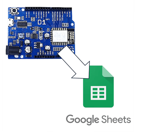
It could have been done using a regular Arduino Uno, but I decided to try the Wemos D1 R2 with built-in WiFi and struggled quite a bit.
This article is for those using Arduinos like the D1 R2 with different pin mappings.
1. IDE Setting
Due to the various types of Arduinos, you also need to install the board package suitable for each board.
Go to File-Preferences in the Arduino IDE.

Then add the following URL to the Additional Boards Manager.
https://arduino.esp8266.com/stable/package_esp8266com_index.json
Then search for D1 R2 in the board package on the left and install it.

Finally, match the USB port and board type correctly and you're done.

2. What are Pins like D1, D2?
The most confusing thing when connecting the WeMos D1 R2 was the pin numbers.
Boards like the Arduino Uno have a relatively simple structure, so the board pin number matches the pin number in the Arduino IDE.
For example, if you want to set pin 4 of the Arduino as output and pin 5 as input, you can do it as follows:
int outputPin = 4;
int inputPin = 5;

void setup(){
    pinMode(outputPin, OUTPUT);
    pinMode(inputPin, INPUT);
}
However, if you apply this directly to the Wemos D1 R2, it won't work.
This is because of a different pin number system.
This is because on the Wemos board, names like D1, D2 are mapped differently from numbers in the IDE.
#define outputPin D4
#define inputPin D5

void setup(){
    pinMode(outputPin, OUTPUT);
    pinMode(inputPin, INPUT);
}
So why does this Arduino have such a structure?
3. GPIO Pins and Arduino Pin Mapping
Looking at the Arduino Uno, you can see a large chipset embedded in it.
Think of this as the CPU, the processing unit, in terms of a computer.
The pins attached to the side of the Arduino are thought to be assigned to each leg of the Arduino chipset.

The picture below shows which leg of the chipset each pin is assigned to.
Out of these connecting pins, the pins that can output or input digital signals are called GPIO pins.
GPIO is short for General Purpose Input/Output.

In the case of the Arduino Uno, you can see that the GPIO pins almost match the board's pin numbers.
So you can run the code without issue if you enter the pin numbers as written in the IDE.
4. Pin Mapping of Wemos D1 R2
The D1 R2 board has a basic chipset along with a WiFi module.
Some of the chipset's pins are used for communication with the WiFi module, limiting the number of pins available for input and output.
When placing the remaining pins on the Arduino board, the GPIO numbers are assigned in no order, causing issues.

As a result, the board manufacturer logically renumbered each pin as D0, D1, D2, so users wouldn't be confused, and made it so these numbers could be used 그대로 in the Arduino IDE.
As seen in the pin map image above, numbers like D1, D2 differ from the actual internal GPIO numbers, so be sure to refer to this map when using the pins.
5. Then How Should We Use It?
The board package installed in the Arduino IDE includes definitions for mapping logical pin names like D5, D6 to actual GPIO numbers.
So if you define as #define myPin D5 at the top, the definition #define D5 14 is included internally in the board package, ultimately making myPin point to GPIO14.

#define myPin D5

void setup(){
    pinMode(myPin, OUTPUT);
}
Then you can use it just like a regular pin.
However, be cautious as some pins are related to booting or flashing.
Board Pin (Dn) | Actual GPIO Number | Remarks |
|---|---|---|
D0 | GPIO16 | |
D1 | GPIO5 | I2C SCL |
D2 | GPIO4 | I2C SDA |
D3 | GPIO0 | Boot related pin, caution |
D4 | GPIO2 | Built-in LED |
D5 | GPIO14 | SPI SCK |
D6 | GPIO12 | SPI MISO |
D7 | GPIO13 | SPI MOSI |
D8 | GPIO15 | Boot related pin, caution |
RX | GPIO3 | Serial receive |
TX | GPIO1 | Serial transmit |
6. Concluding the Article

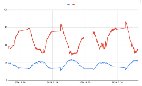
Last time I used the D1 R2, I only added a simple temperature and humidity sensor, so it wasn't too difficult.
This time, as I connected more pins, I learned a few new things.
I'm considering running a maker club next year.

댓글을 불러오는 중...